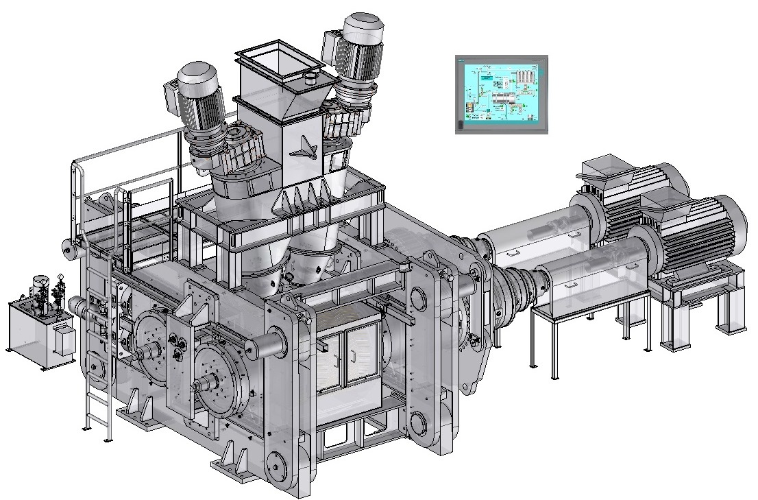
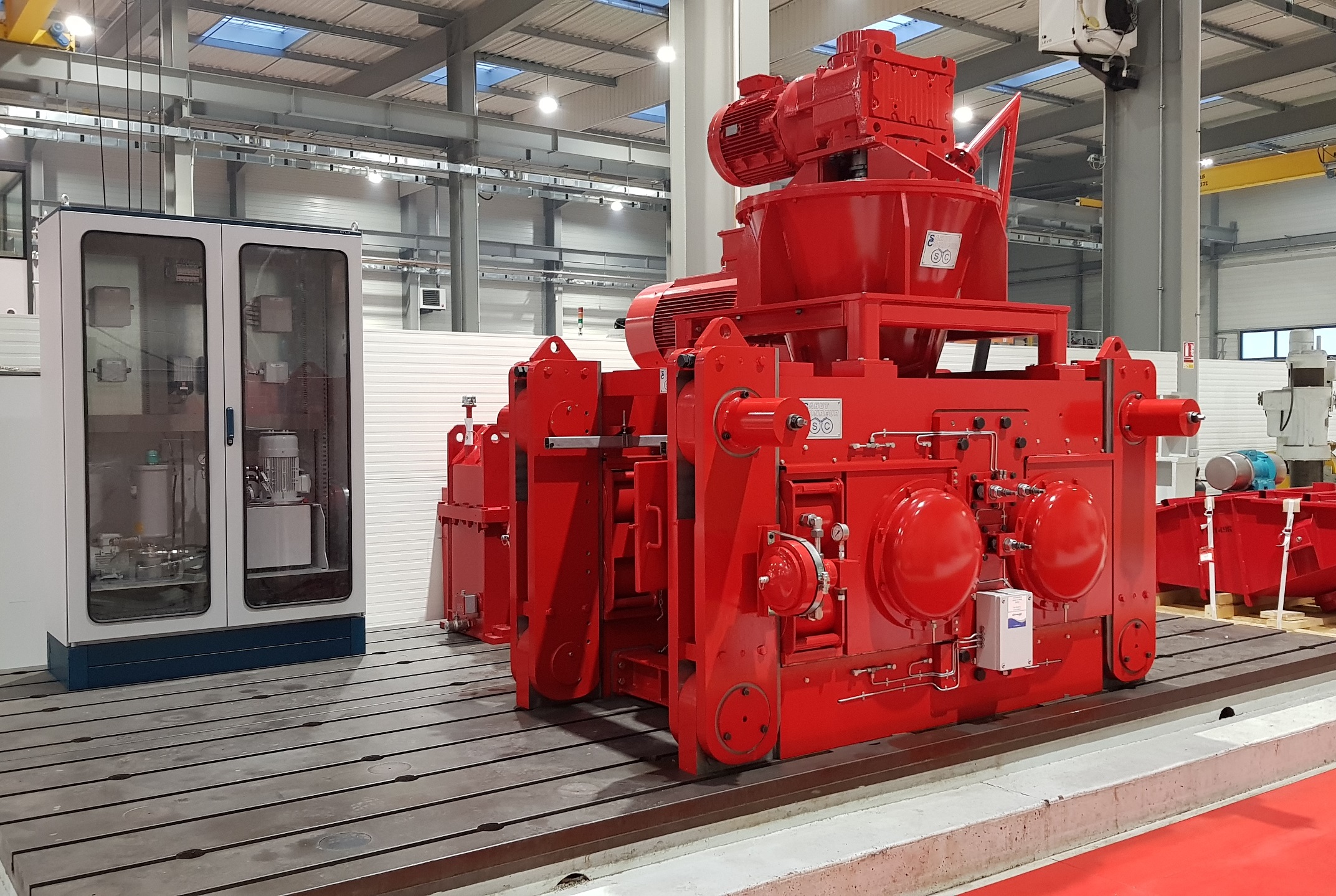
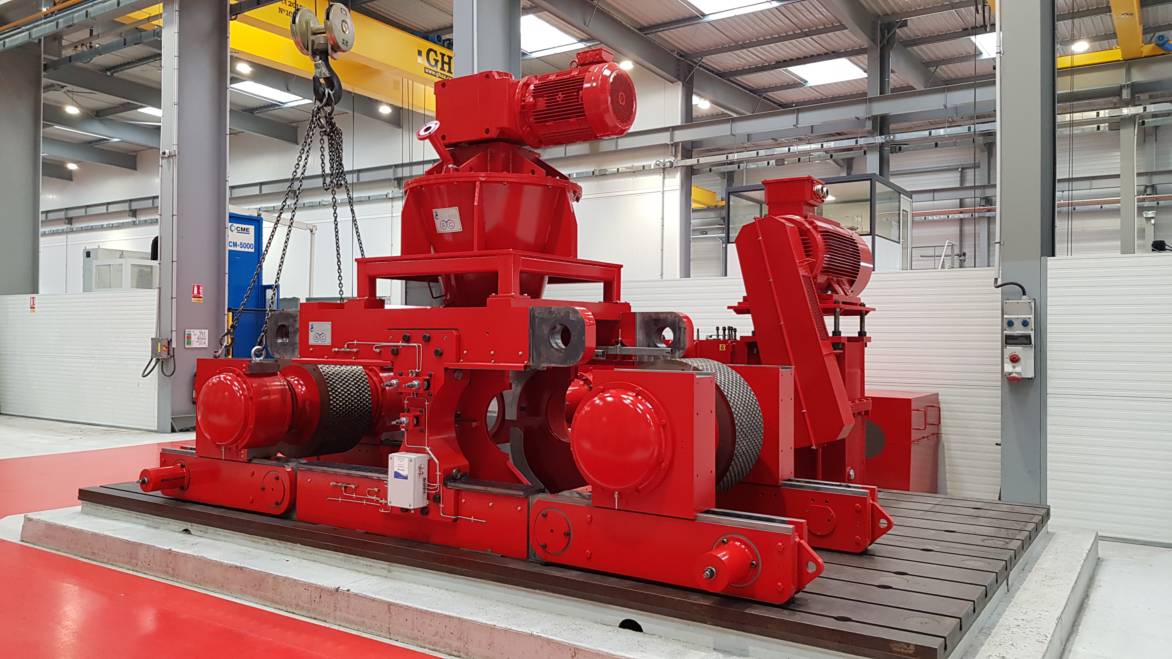
Compactor
SAHUT‐CONREUR
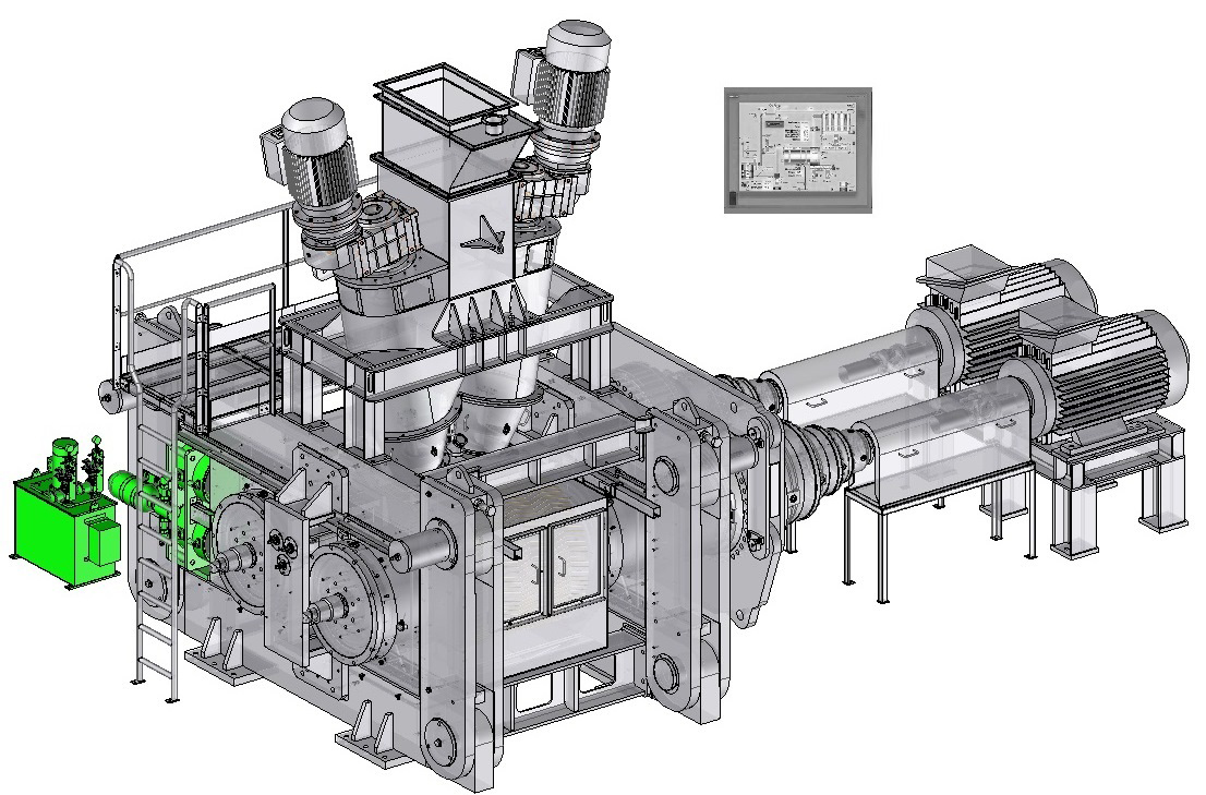
designs and manufactures compactors for heavy-duty operation under hard and difficult conditions, with reliable use and minimal maintenance. Click on the different parts of this compactor to discover its main components.Dynamic view
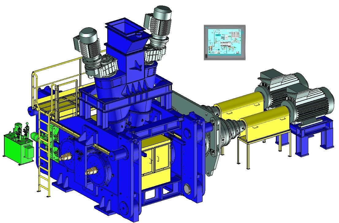
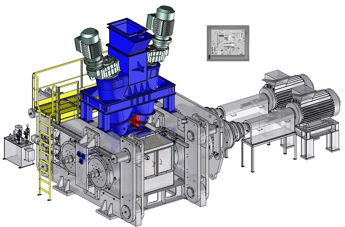
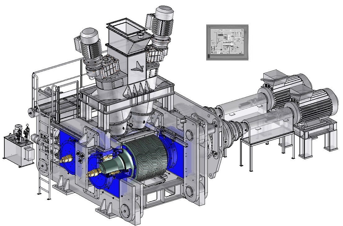
Feeding system
The feeding system is essential for the full compactor efficiency:SAHUT-CONREUR
has developed 2 types of systems selected according to the product processed: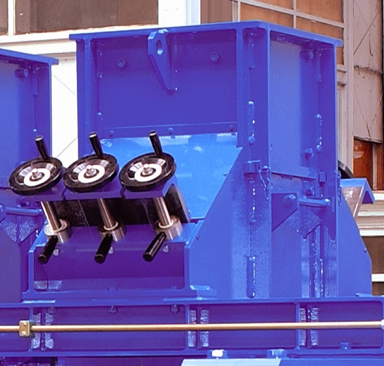
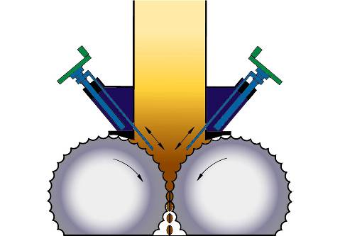
The hopper
Feeding the rolls by gravity, this system can, if necessary, be fitted with inclined flaps whose the position is manually or automatically adjusted.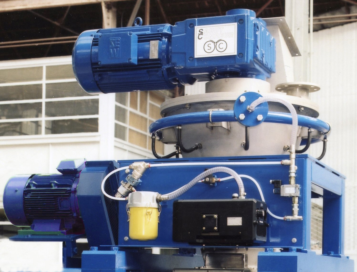
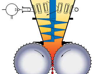
The force-feeder equipped with one or two conical screws
Predensifying the product and feeding the rolls. For very aerated products, the force feeder can be equipped with a deaeration system (vacuum pump) to remove the air contained in the product.
These 2 feed systems can be equipped with special floating cheek plates reducing the powder leakage on the roll sides and providing a better efficiency in the densification area.
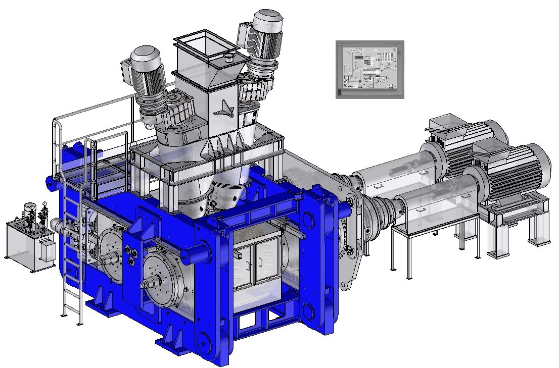
Rolls
Rolls surface
The compactor is composed of two rolls: one is fixed in the compactor frame (fixed roll) whereas the other roll can move perpendicularly to its axis (mobile roll) varying the space between them. The size of a compactor is characterized by the roll diameter (from 150 mm to 1400 mm) and the roll width (from 30 mm to 1200 mm).
Three technological solutions are possible for the working surface of the rolls:
Three technological solutions are possible for the working surface of the rolls:
- shafts with pocketed tyres (steel rings heat-shrunk on the shafts) – in option with cooling system.
- shafts with bolted segments (the segments are linked with the shaft by 2 clamping rings) – in option with cooling system.
- profiled monobloc shafts – in option with cooling system.
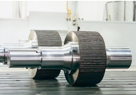
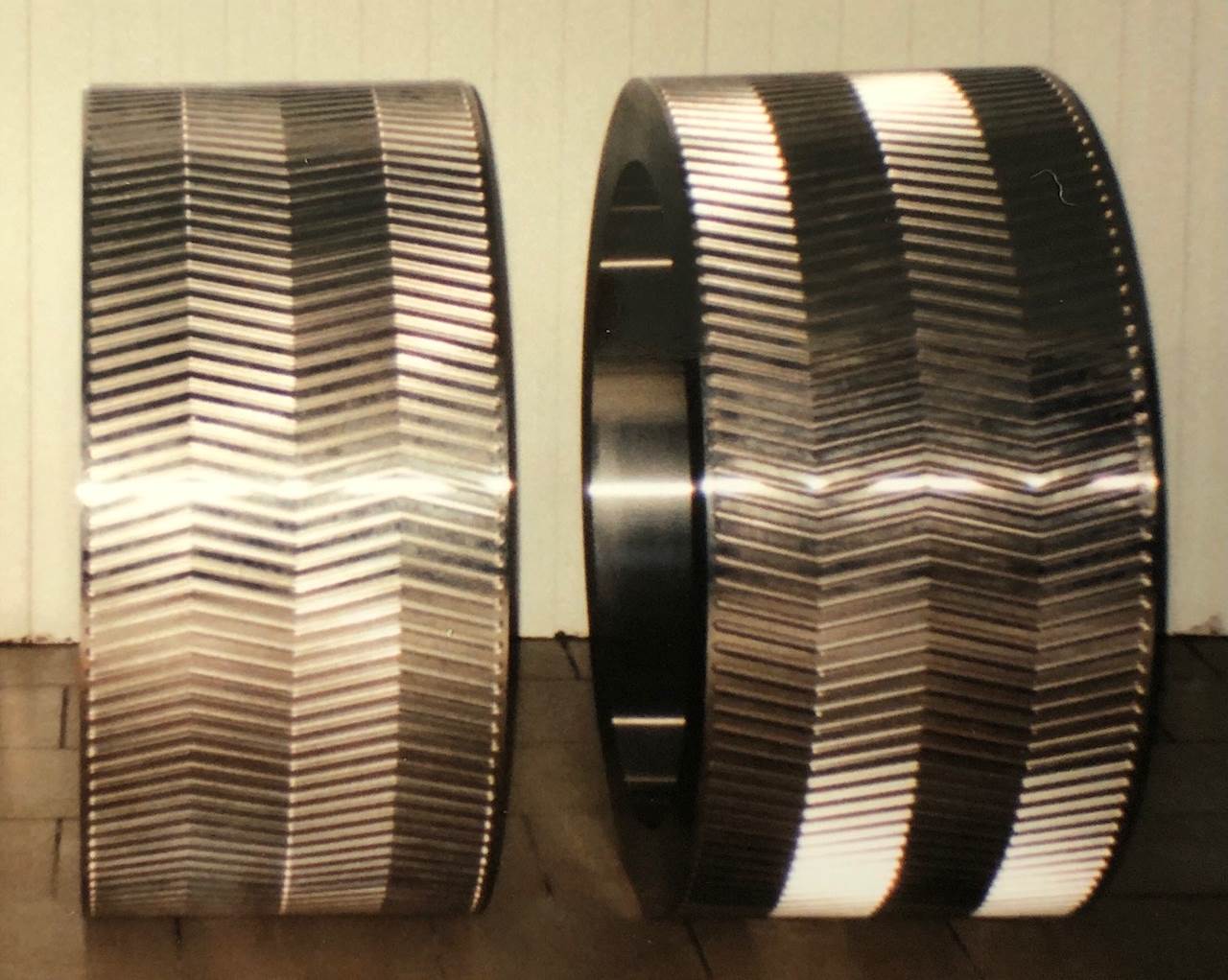
Special treated materials (alloy steel, stainless steel, cast iron, special thermal treatment…) are used for the manufacture of tyres and segments, dictated by the product abrasiveness, its corrosive effect and the compaction conditions (product temperature, compaction pressure).
Rolls bearing
These rolls are mounted on heavy-duty bearings sized for a long life-time, manually or automatically lubricated by grease or oil. For particular applications, the cooling of shafts and bearings can be installed.Frame
Usually the compactor is composed of a special steel frame machined and assembled with a sufficient mass for heavy-duty operation under high pressure.However, in order to remove easily the rolls and carry out maintenance operation, a hinged frame can be installed. This system allows the replacement of rolls without dismantling the feed system and the components above the rolls.
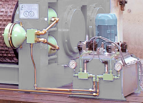
Hydraulic System
The compactor is equipped with an hydraulic system able to apply a force on the mobile roll by means of jacks. This force can be different in certain cases on each bearing block of the mobile roll thanks to a double hydraulic circuit. This system also includes safety devices and nitrogen accumulators to dampen the movement and quick return of the mobile roll and protect the compactor when tramp material is inadvertently fed to the rolls.
The force applied on the product can vary from 5 to 120 KN/cm.
The force applied on the product can vary from 5 to 120 KN/cm.
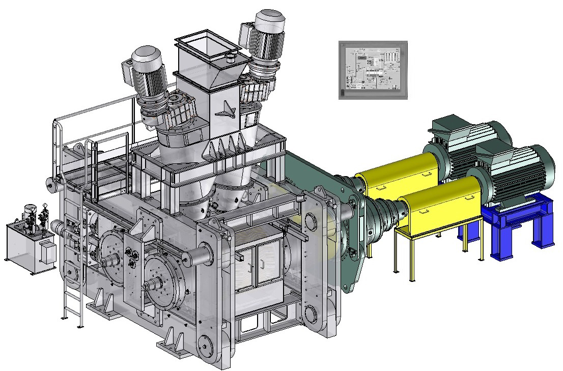
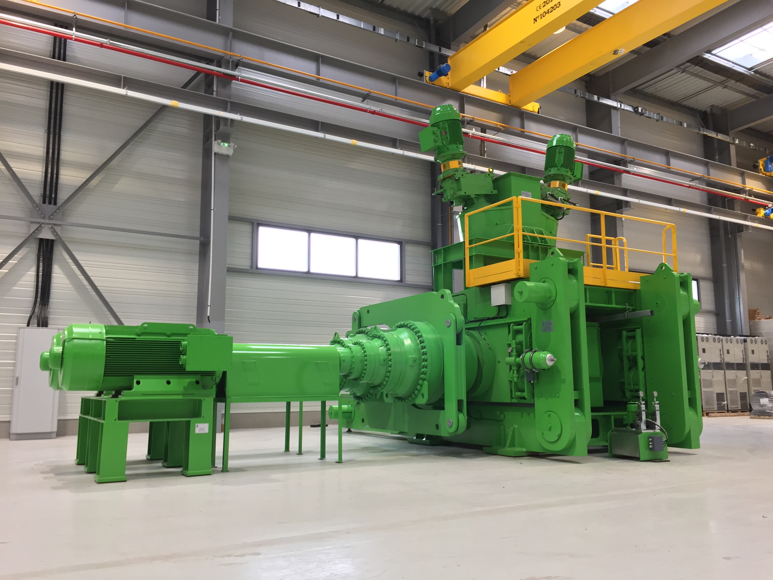
Rolls drive
The compactor is equipped with a special double-output gear-box and internal gear couplings able to withstand the axial misalignement caused by the mobile roll movement. The rolls speed can go up to 25 Rpm and even higher in particular cases; it corresponds to a tangential rolls speed up to around 1,5 m/s.
In particular cases (high torque, restricted space,…) other drive systems (planetary gear-box, hydraulic motor) can be used.
In particular cases (high torque, restricted space,…) other drive systems (planetary gear-box, hydraulic motor) can be used.
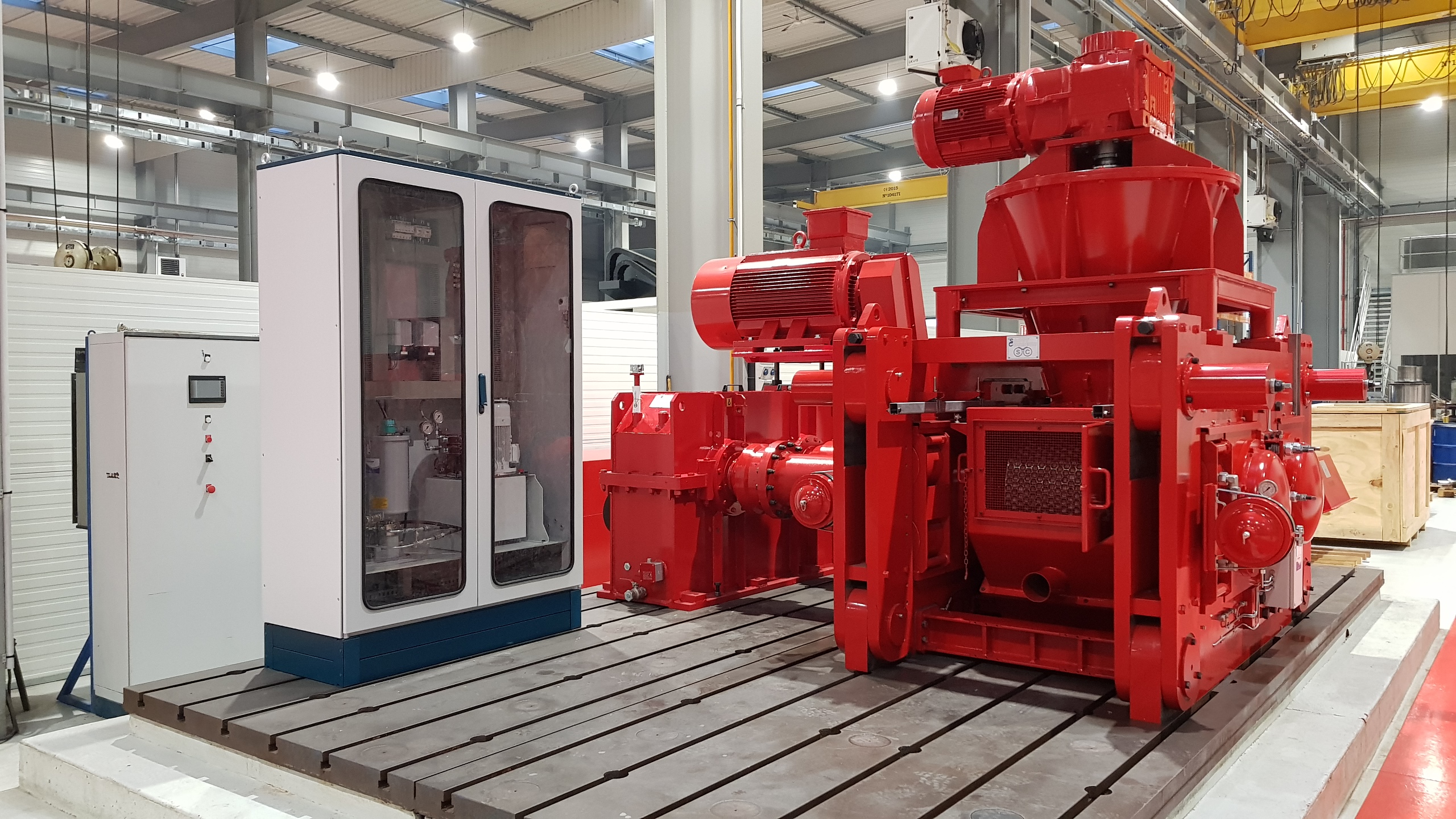
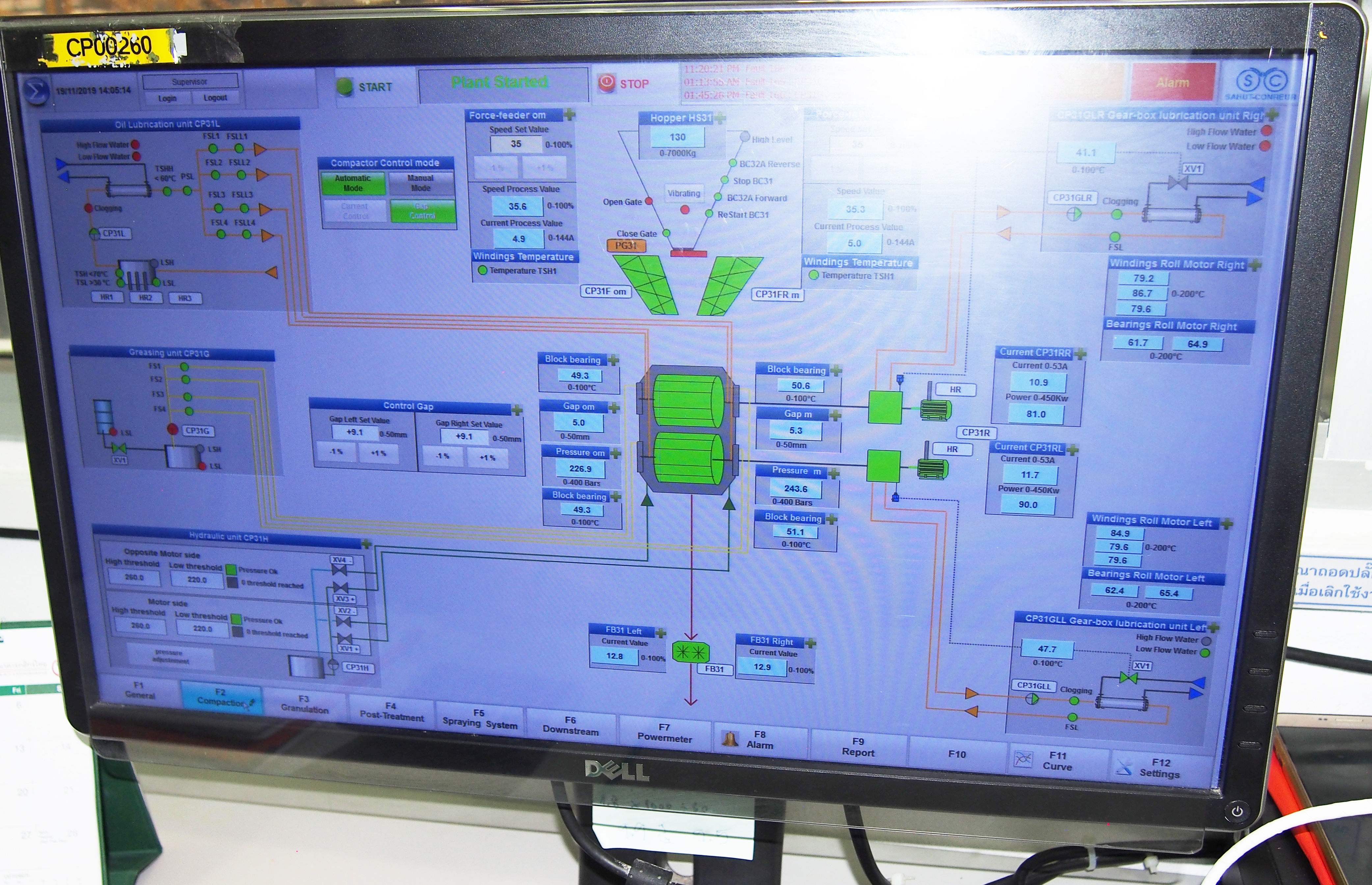
Control-automation
A high automation level ensures constant continuous operation of the compactor without operator. The control-drive system is based on signals from the measurement of the rolls gap, the compaction pressure value and the force-feeder/rolls drive speeds and powers absorbed.
In case of hopper with flaps installed as feed system, two means of control can be installed on the compactor:
- Either control of power consumed by the rolls drive by positioning of the feed flaps.
- Or control of rolls gap by positioning of the feed flaps. In case of force-feeder installed as feed system, two means of control can be installed on the compactor :
- Either control of power consumed by the rolls drive by adjusting the speed of the screw shaft.
- Or control of rolls gap by adjusting the speed of the screw.