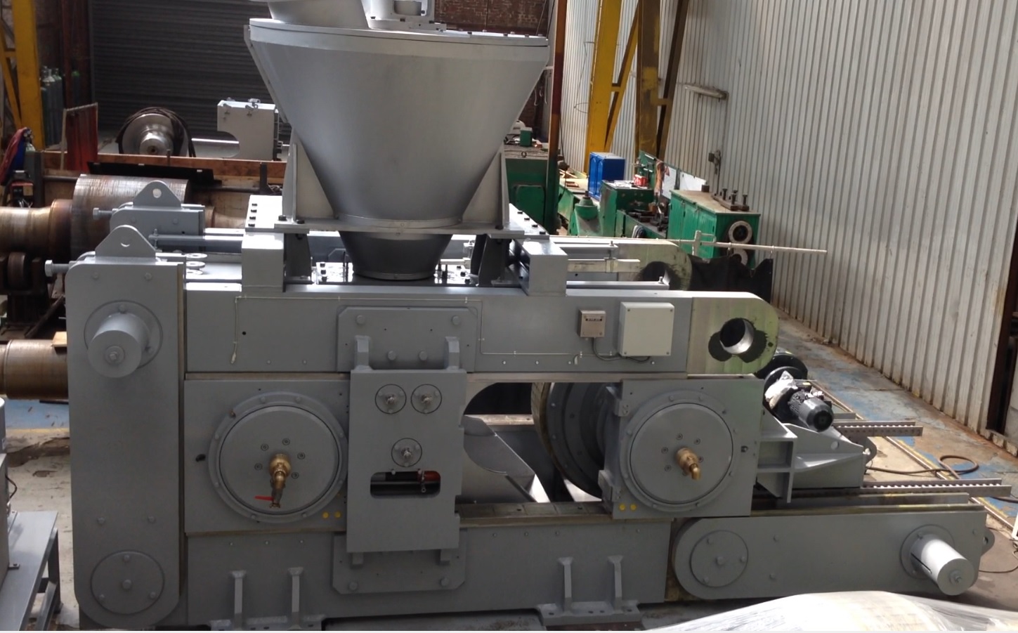
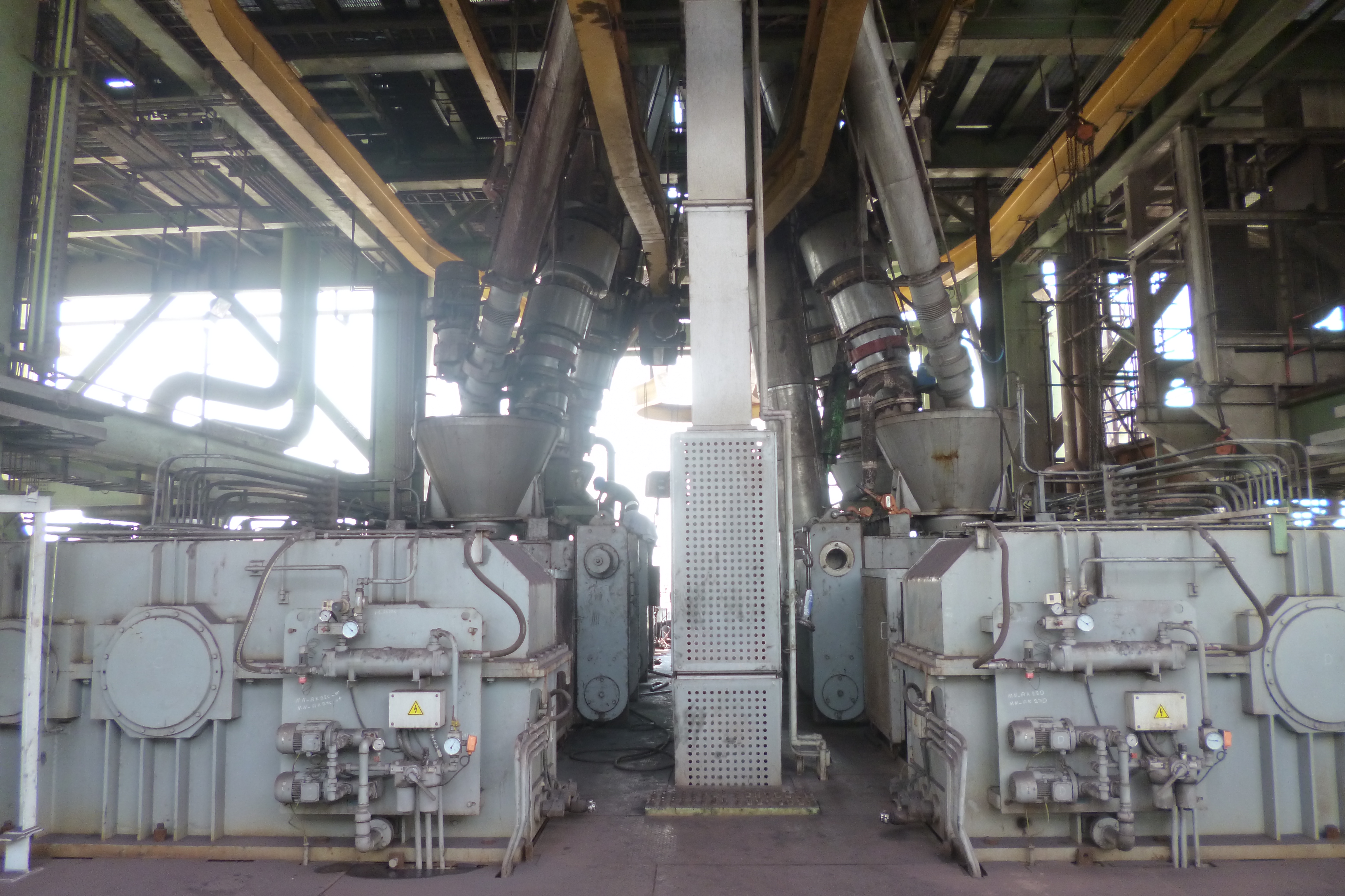
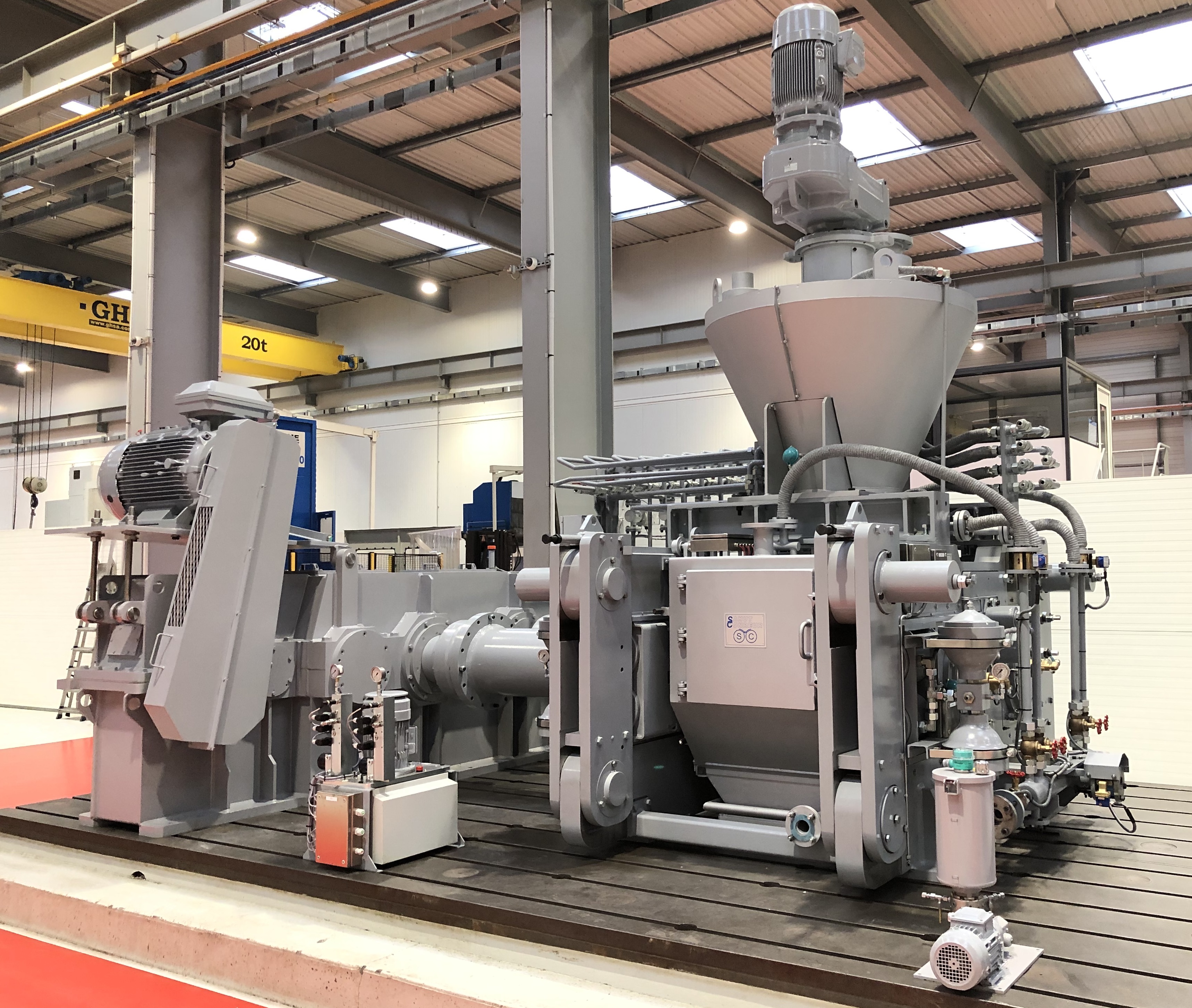
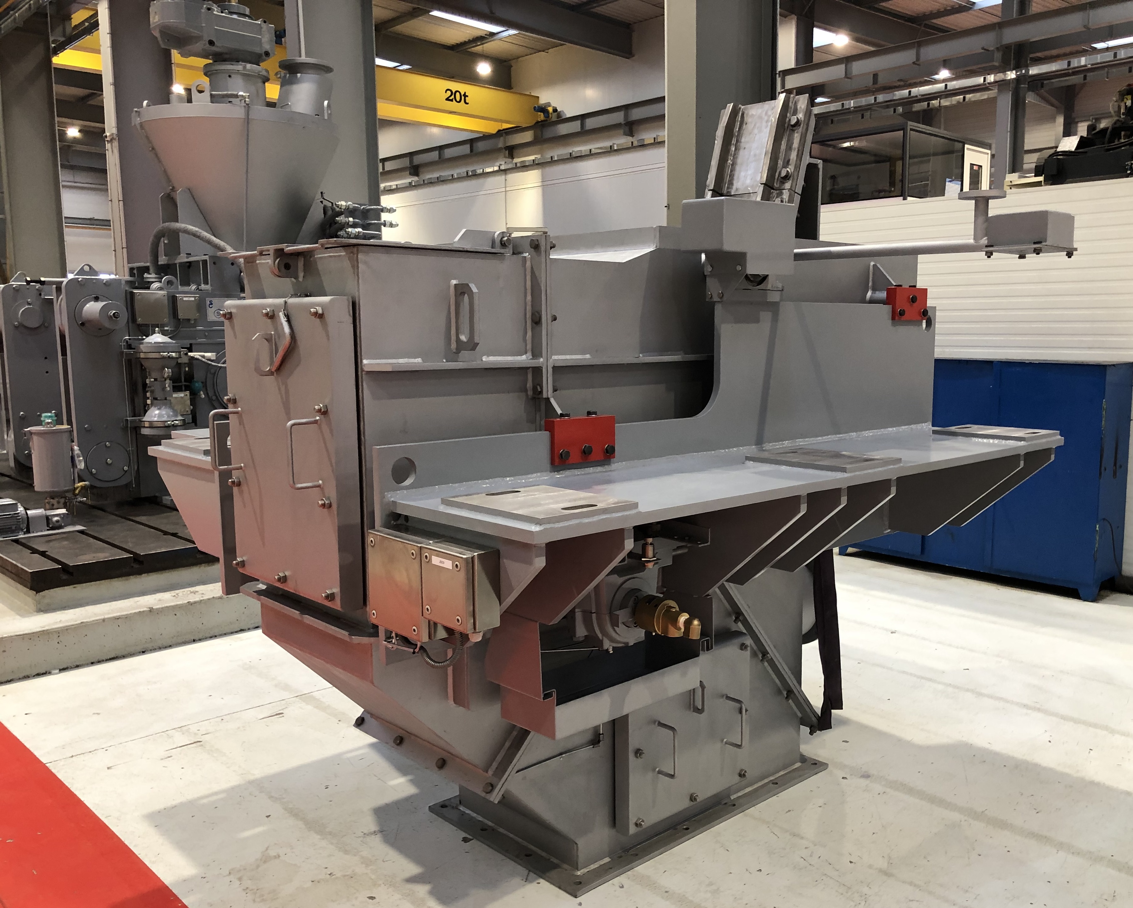
Hot briquetting press
SAHUT‐CONREUR
designs and manufactures hot briquetting presses and separators for heavy‐duty operation under hard and difficult conditions, with reliable use and minimal maintenance. Compared to briquetting presses used for cold briquetting application, hot briquetting presses (and separators) are fitted with special dispositive to comply with the hot material:- Parts in contact with the product are manufactured from special refractory stainless steel.
- Water cooling system installed on the heat‐sensitive parts.
- Seal gas system for injection in defined zone to avoid the DRI re‐oxidation.
- Powerful sub elements (rolls drive, force‐feeder drive, rollers bearings, hydraulic system, press frame,…)
- Equipment’s parts adapted to accept thermal dilatation.
- Instruments design for high temperature and flammable resistant.
- Additional instruments installed to control and protect the equipment.
- Special surface treatment on the parts of the equipment.
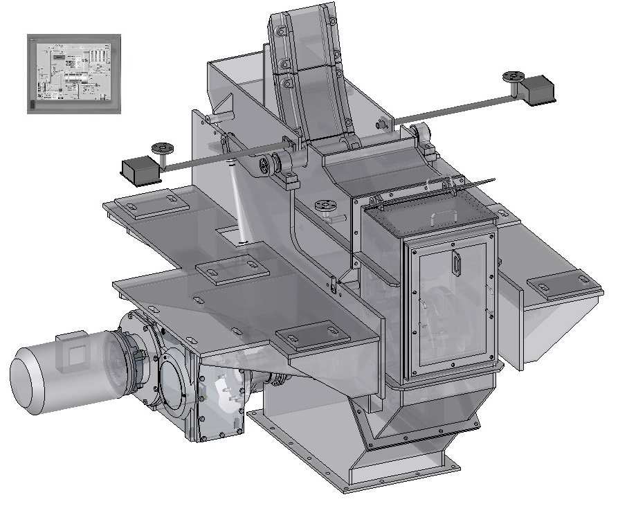
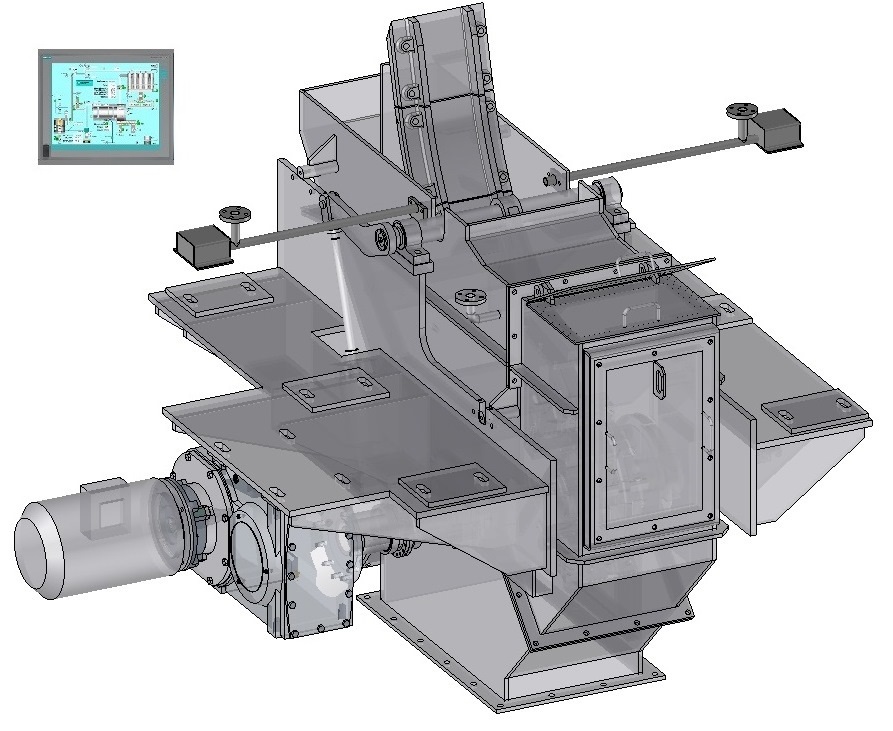
Dynamic view
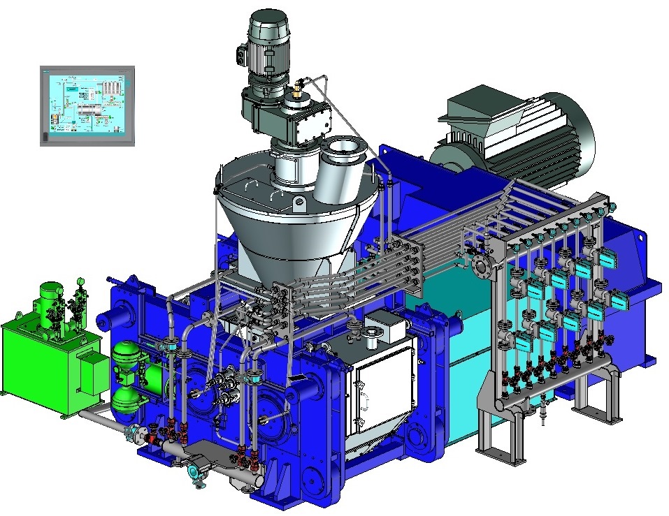


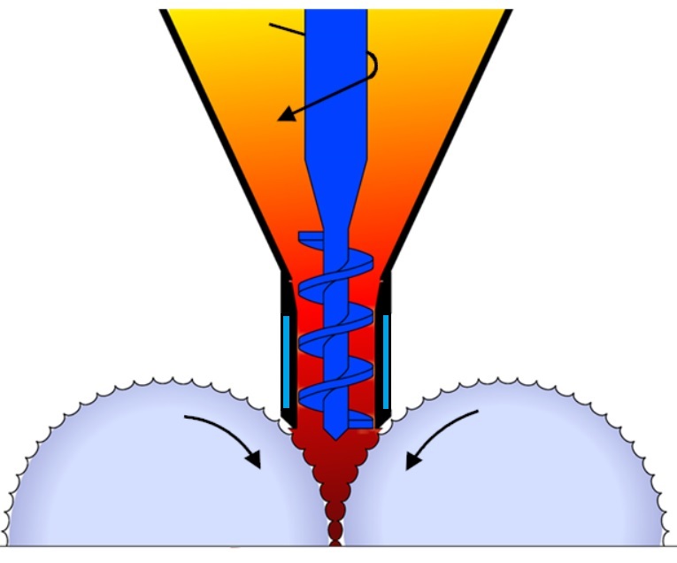
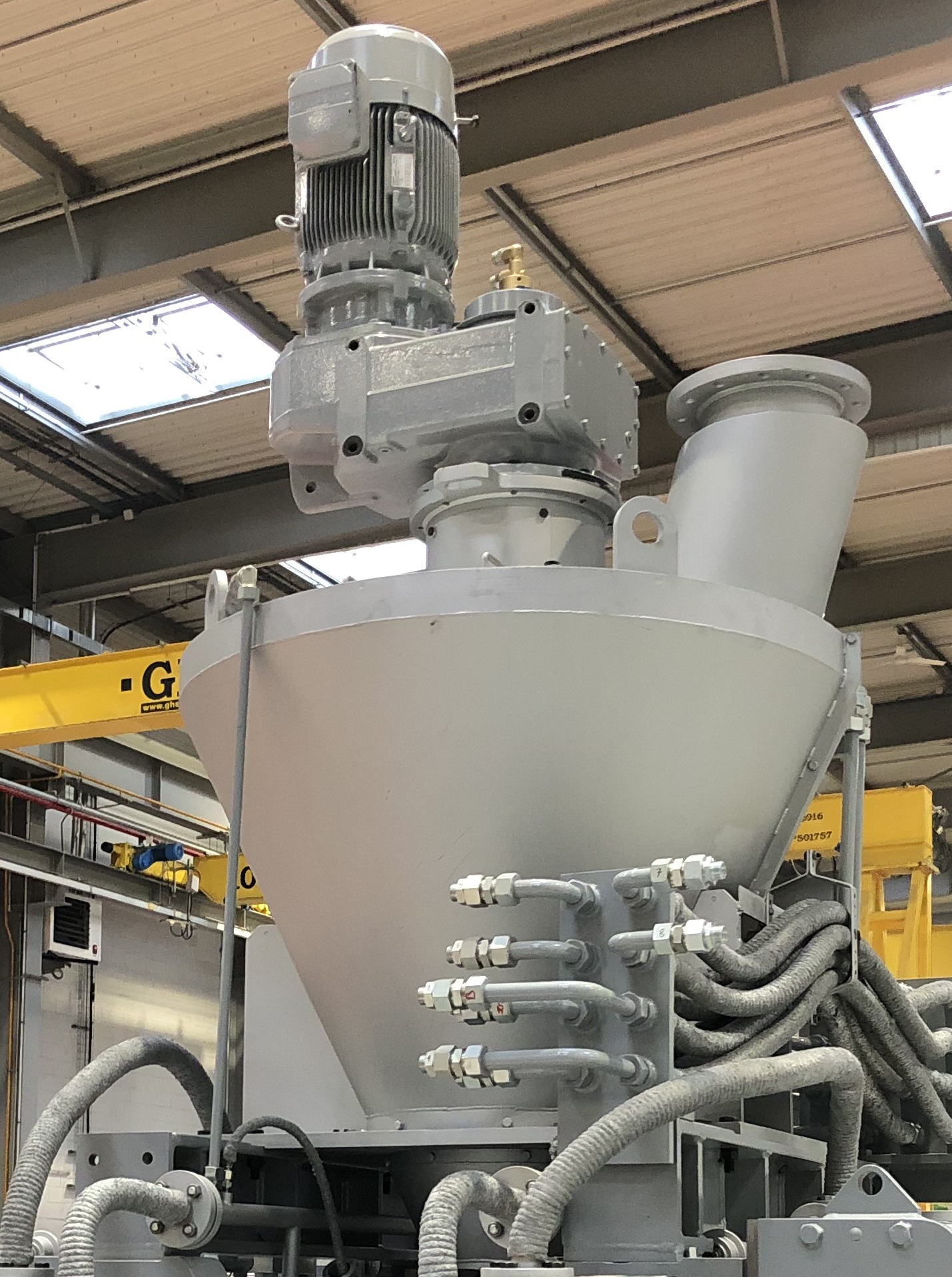
Feeding system
The feeding system is essential for the hot briquetting press efficiency:SAHUT‐CONREUR
has developed a force‐feeder equipped with one screw specially adapted for degasing and predensifying the hot DRI and feeding the rolls.Made of special refractory stainless steel adapted to the high temperature, the force‐feerder tank is also thermally insulated. A cooling water system is installed for the force‐feeder tank and the screw shaft. Seal gas system is also injected in these parts to avoid re‐oxidation of the DRI.
The force‐feeder screw shaft is driven by a variable speed gear‐electric motor installed at the end of screw shaft. One frequency inverter installed in the MCC adjusts permanently the speed of the screw shaft through a control loop design in the Control‐ Drive cabinet.
This feed system is also equipped with special floating cheek plates system reducing the powder leakage on the roll sides and providing a better efficiency in the densification area. In order to preserve the life time of the cheek plates, there is also internal water cooling.
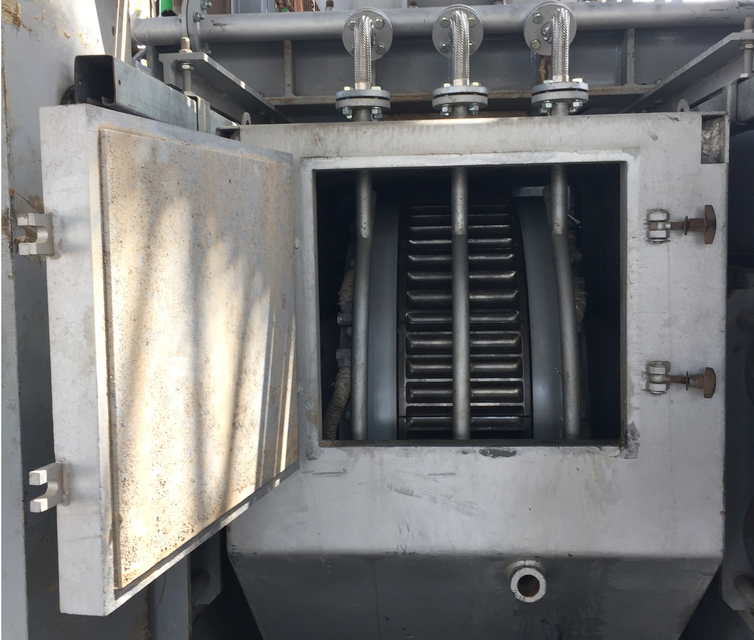
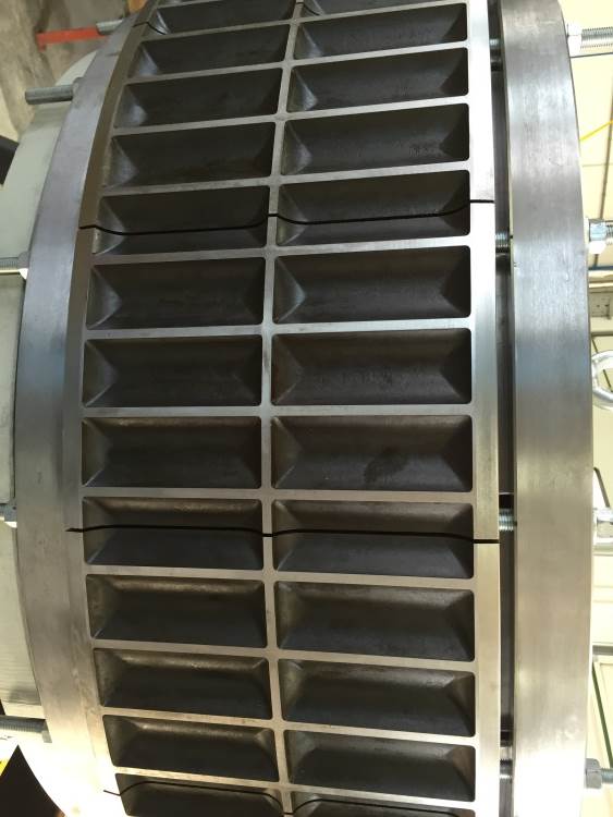
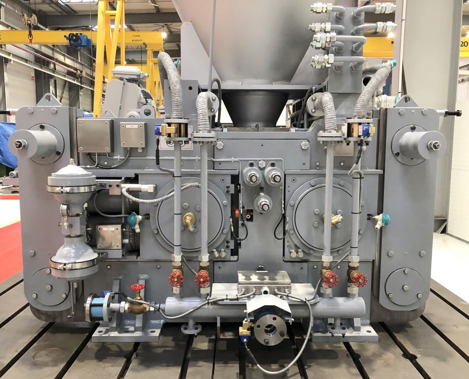
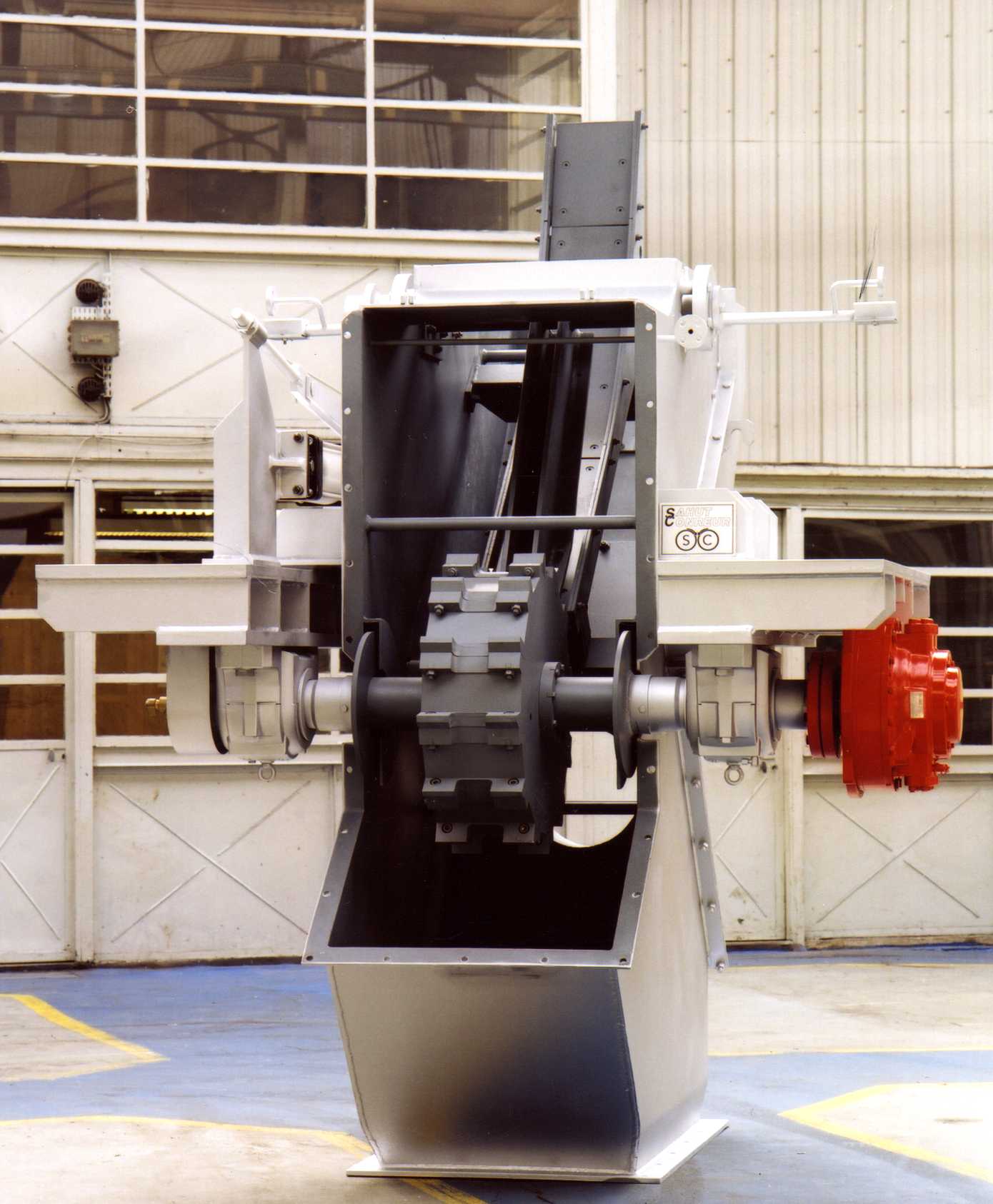
Rolls
Rolls surface
The hot briquetting press is composed of two rolls: one is fixed in the press frame (fixed roll) whereas the other roll can move perpendicularly to its axis (mobile roll) varying the space between them. The size of a hot briquetting press is characterized by the roll diameter (from 400 mm to 1400 mm) and the roll width (from 100 mm to 400 mm).Two technological solutions are possible for the working surface of the rolls:
- shafts with pocketed tyres with cooling system (steel rings heat‐shrunk on the shafts)
- shafts with bolted segments (the segments are linked with the shaft by 2 clamping rings).
In both cases, special hardening treated materials (special steel, cast iron, special thermal treatment…) are used for the manufacture of tyres and segments, specially dictated by the DRI abrasiveness, corrosive effect and the hot briquetting conditions (product temperature, briquetting pressure).
Rolls bearings
These rolls are mounted on heavy‐duty bearings sized for a long life‐time, automatically lubricated by grease. The bearings are also water‐cooled.Frame
The hot briquetting press is composed of a
steel frame machined and assembled with
a sufficient mass for heavy‐duty operation
under high pressure.
With a hinged design, the frame installed
on the hot briquetting press allows a quick
replacement of rolls for maintenance
purpose without dismantling the feed
system and the components above the
rolls.
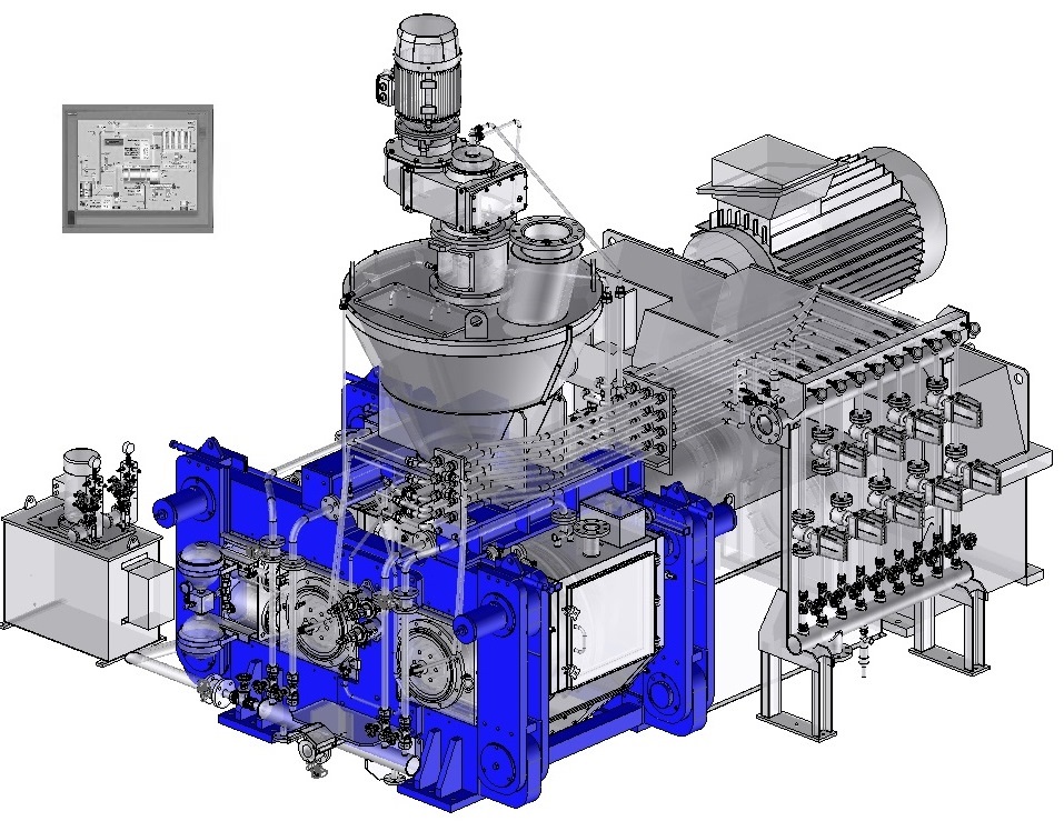
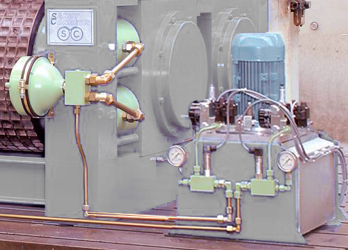
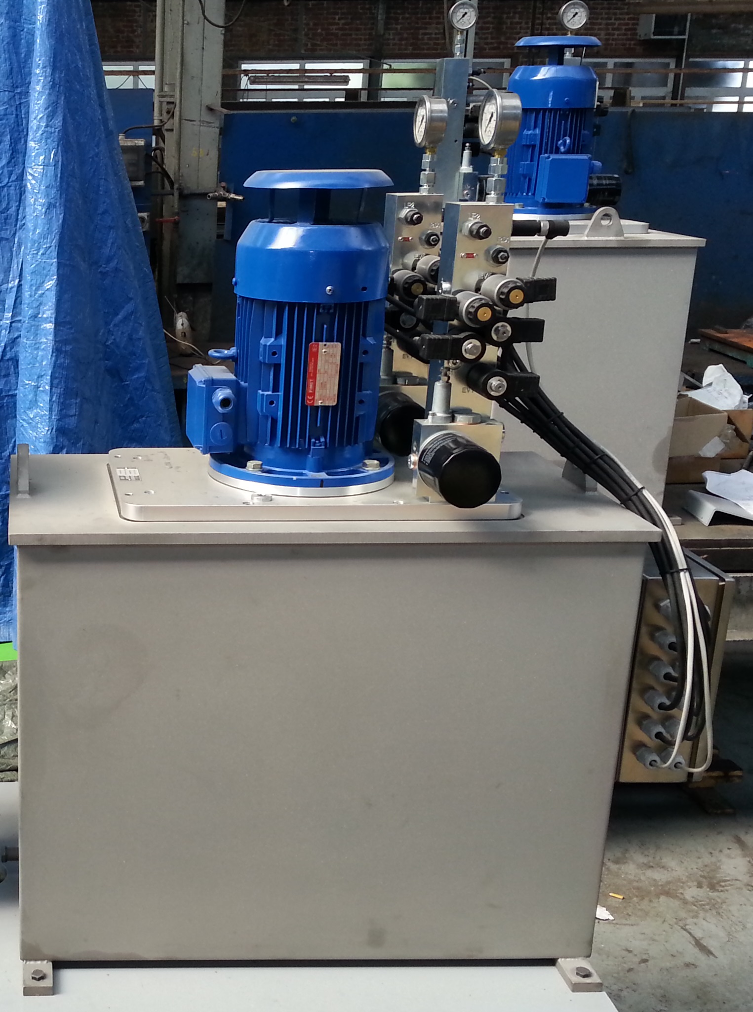
Hydraulic System
The hot briquetting press is equipped with an hydraulic system able to apply a force on the mobile roll by means of jacks. This force can be different in certain cases on each bearing block of the mobile roll thanks to a double hydraulic circuit. This system also includes safety devices and nitrogen accumulators to dampen the movement and quick return of the mobile roll and protect the briquetting press when tramp material is inadvertently fed to the rolls.The force applied on the product can be up to 180 KN/Lcm.
Rolls drive
The hot briquetting press is equipped with a special double‐output gear‐box and internal gear couplings able to withstand the axial misalignment caused by the mobile roll movement. The coupling of the mobile roll is fitted with a device for circumferential adjustement of the rolls that provides a perfect synchronisation of pockets between the fixed roll pockets and those of the mobile roll.The rolls drive is ensured by main electrical motor mounted on a frame controlled through a variable frequency drive mounted in the MCC.
The tangential rolls speed can go up to approx. 0.75 m/s.
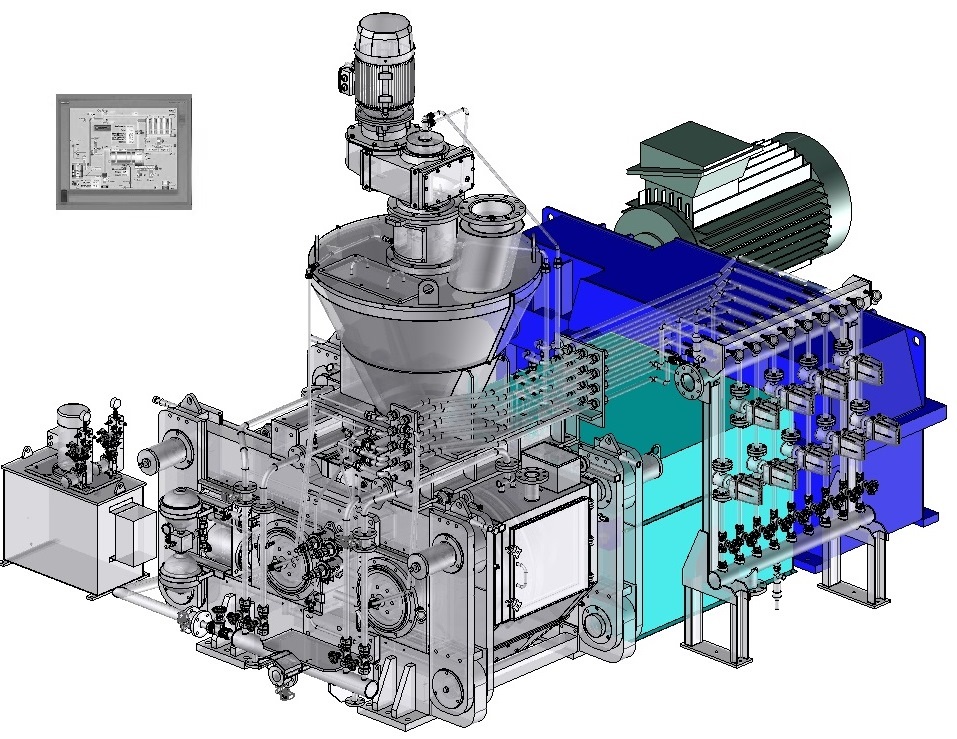
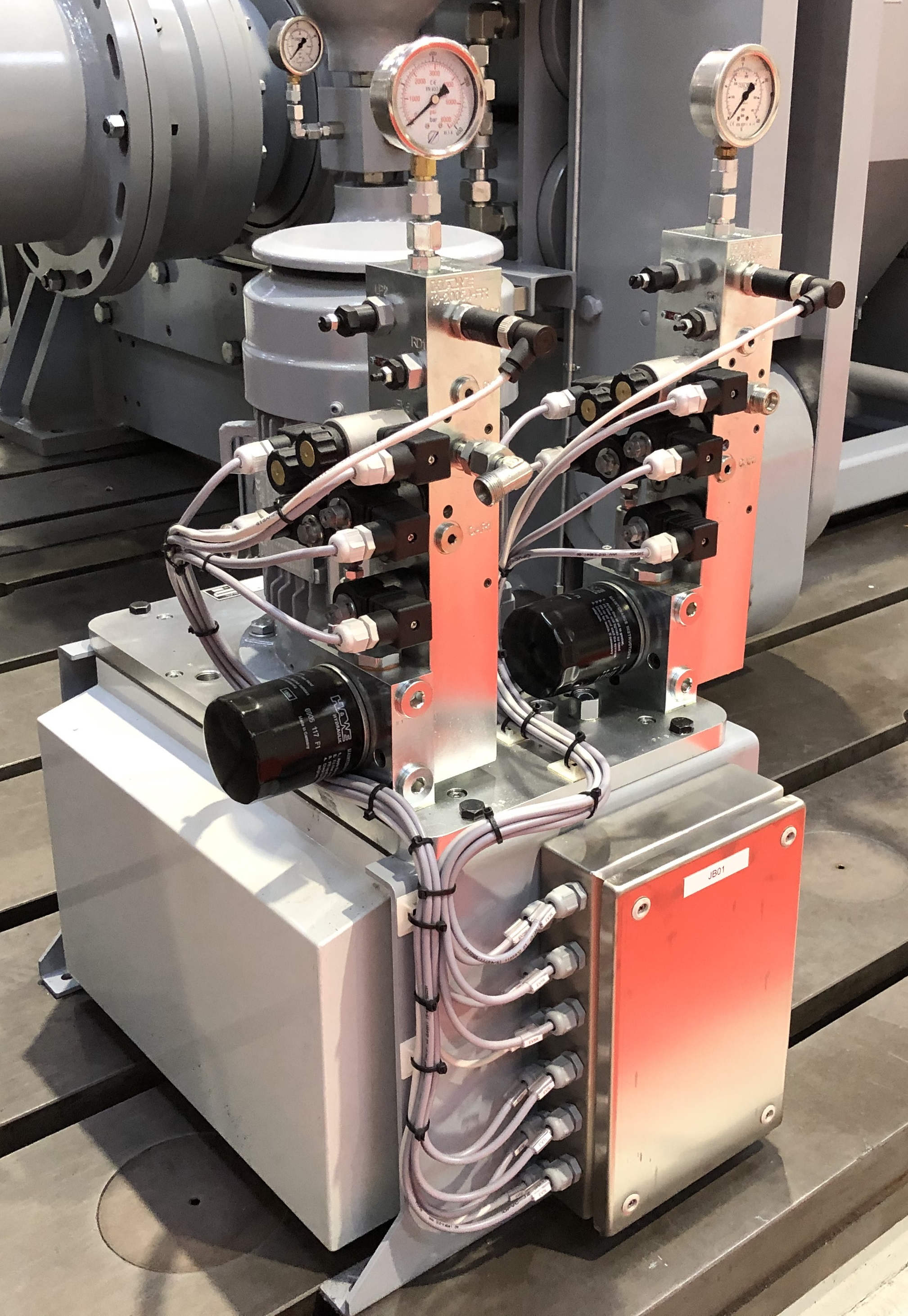
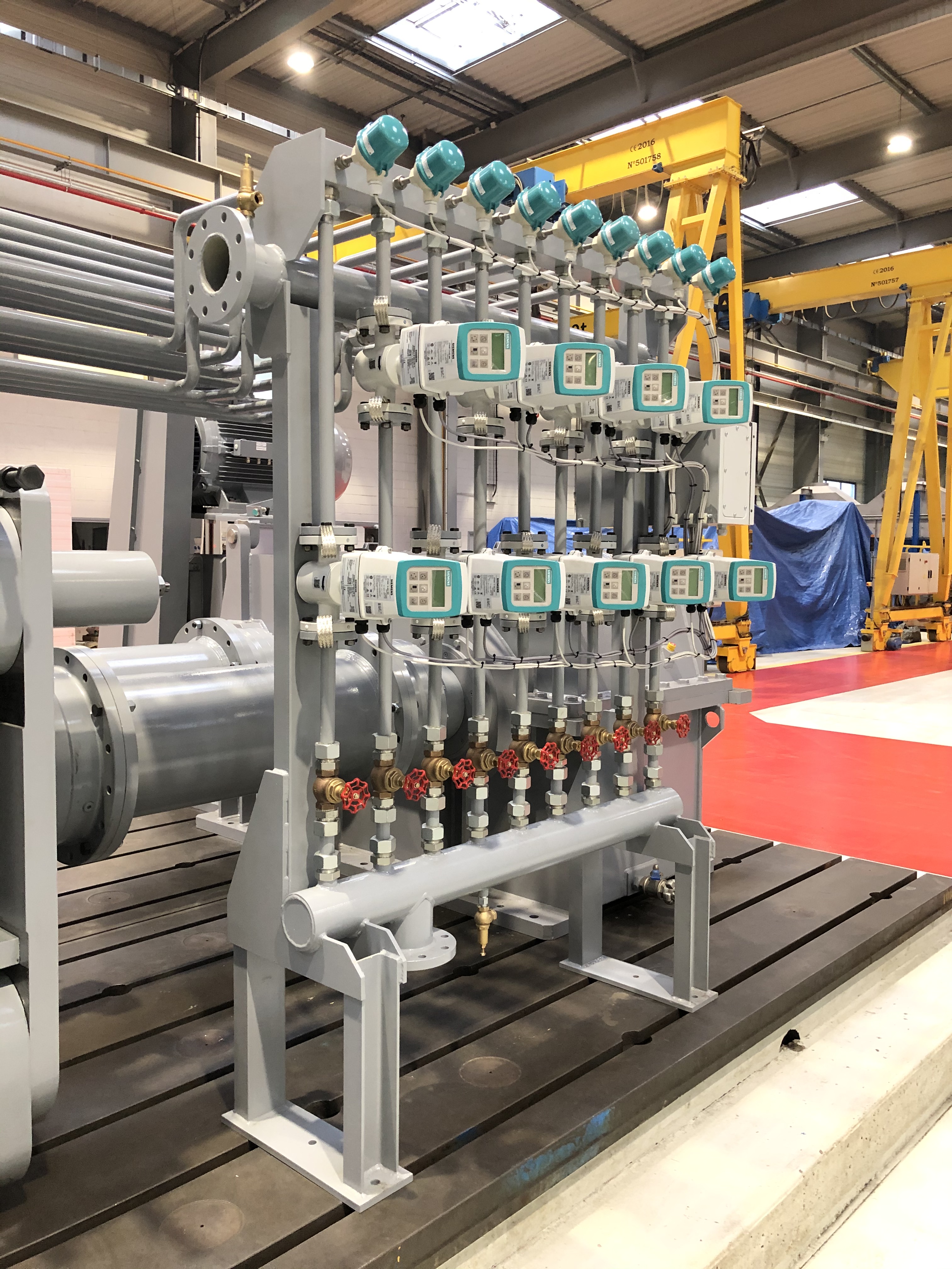
WATER COOLING SYSTEM & SEAL GAS SYSTEM
Considering the high temperature of the material and in
order to protect the hot briquetting press, its main parts
are protected by a cooling water system.
Fitted with networks pipes, a set of valves and
instruments (temperature sensors, flowmeters, pressure
switches), this cooling water system is designed to control
and distribute water at required temperature and flow to
each important parts of the hot briquetting press (force‐
feeder shaft and tanks, cheek plates, rolls shafts, rolls
bearings,…)
Considering the presence of sparks during production
caused by the high flammability of the DRI, and to avoid re‐
oxidation of the DRI, an inert gas (like nitrogen) must be
injected in the hot briquetting press to minimize the
oxygen rate of the ambient air (<2%).
Fitted with networks pipes, a set of valves and instruments (flowmeters), this seal gas system is designed to control and distribute seal gas (nitrogen usually) at required flow to defined zone of the hot briquetting press (force‐feeder tank, cheek plates, rolls surface, rolls casing…)
Fitted with networks pipes, a set of valves and instruments (flowmeters), this seal gas system is designed to control and distribute seal gas (nitrogen usually) at required flow to defined zone of the hot briquetting press (force‐feeder tank, cheek plates, rolls surface, rolls casing…)
Control-automation
A high automation level ensures a constant continuous operation of the hot briquetting press. The control‐drive system is based on signals from the measurement of the rolls gap, the briquetting pressure value and the force‐feeder / rolls drive.
Several control loops are combined in the software
programming to ensure a constant and proper running
of the hot briquetting press:
The control‐drive system and associated supervisory developed by
- Control of the power consumed by the rolls drive by adjusting the speed of the screw shaft.
- Control of the power consumed by the for‐feeder drive by adjusting the speed of the screw shaft.
The control‐drive system and associated supervisory developed by
SAHUT‐CONREUR
for controlling the Hot Briquetting Unit integrates the following features:- Industrial SIMATIC PC computer suitable for production applications
- Supervision software type WINCC
- Robustness and high availability
- Data acquisition, management and measuring.
- Exchange table provided to transfer main signals to whole plant DCS


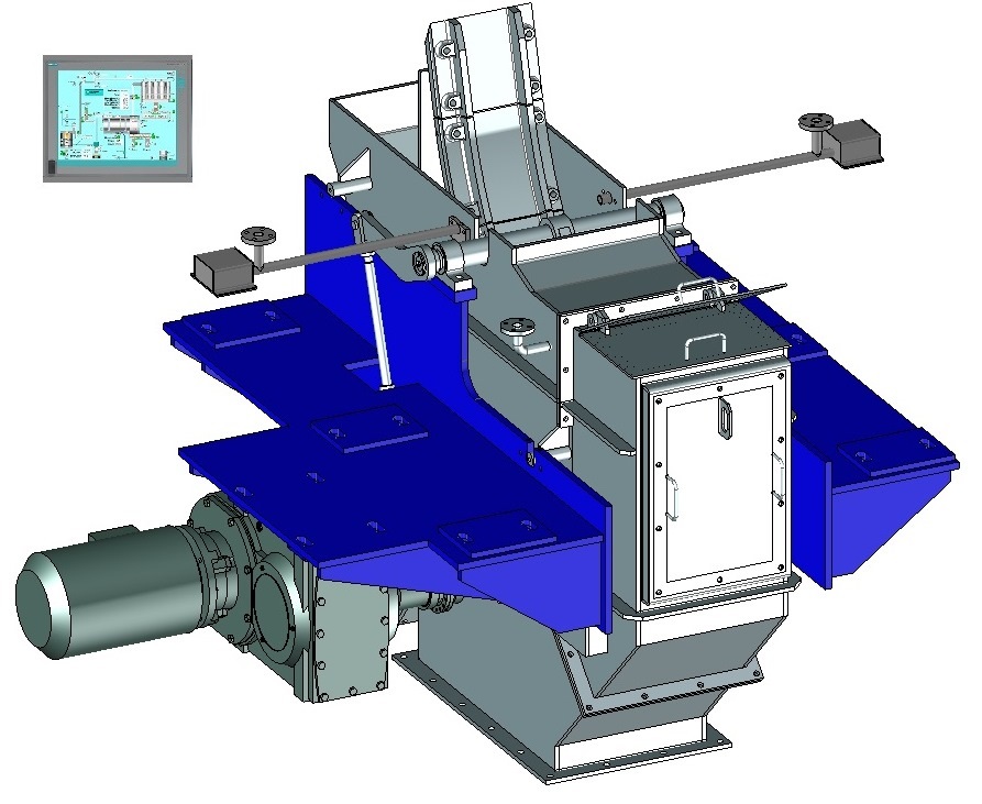
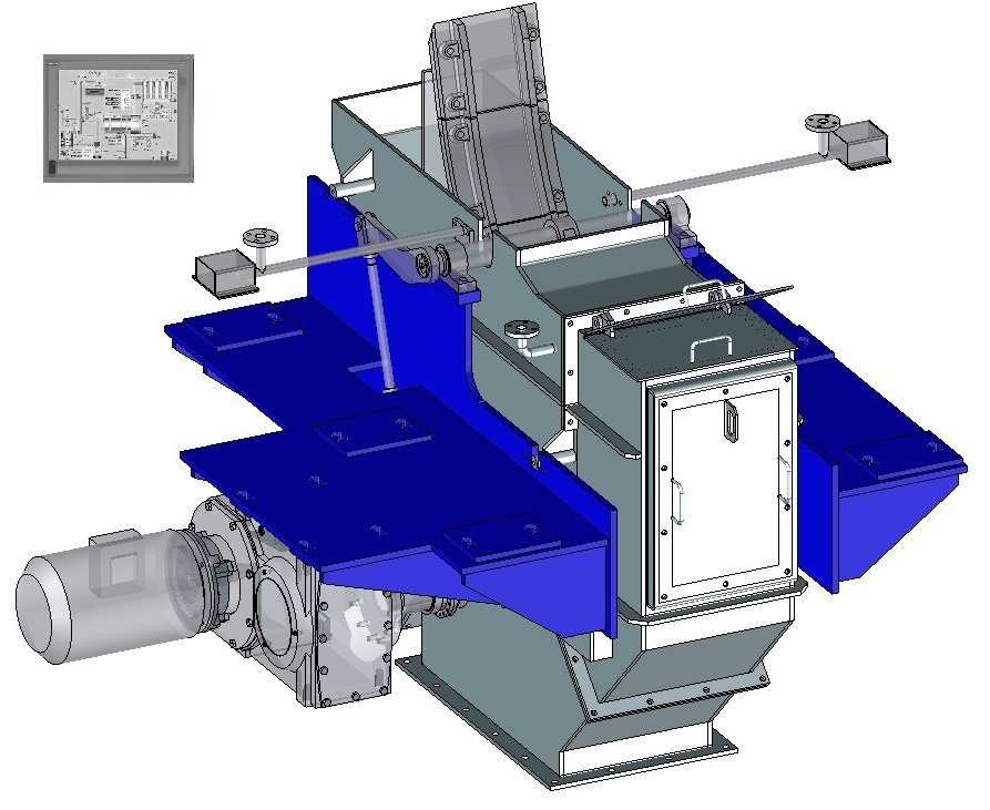
Separator
The separator is installed just under the rolls cover of the hot briquetting press and at the discharge of the briquettes-strips. It is mounted by the steel structure supporting the press.Click on the different parts of this separator to discover its main components:
Dynamic view

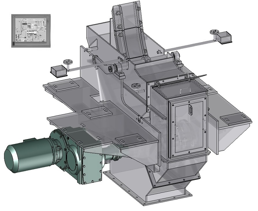
Casing
Made of special refractory stainless steel adapted
to the high temperature, the separator’s casing is
assembled in several parts for easy access and
dismounting‐remounting of the rotor and the
nose.
It is equipped with inert gas injection through the installation of nozzles, labyrinth seals for the shaft, one inspection door and one dust collection flange.
It is equipped with inert gas injection through the installation of nozzles, labyrinth seals for the shaft, one inspection door and one dust collection flange.

Rotor
The separator’s rotor is mounted on 2 blocks bearings placed at the
outside of the casing with an internal cooling system. The rotor is
fitted with one rotor equipped with a set of bolted impact bars. The
impact bars are welded with wear resistant over layer and designed
for easy and quick replacement.
The rotor is supported by two complete block bearings with double‐ row self‐aligning roller bearings and withdrawal sleeves, mounted in steel housings with tightness by labyrinths seals.
The rotor is supported by two complete block bearings with double‐ row self‐aligning roller bearings and withdrawal sleeves, mounted in steel housings with tightness by labyrinths seals.
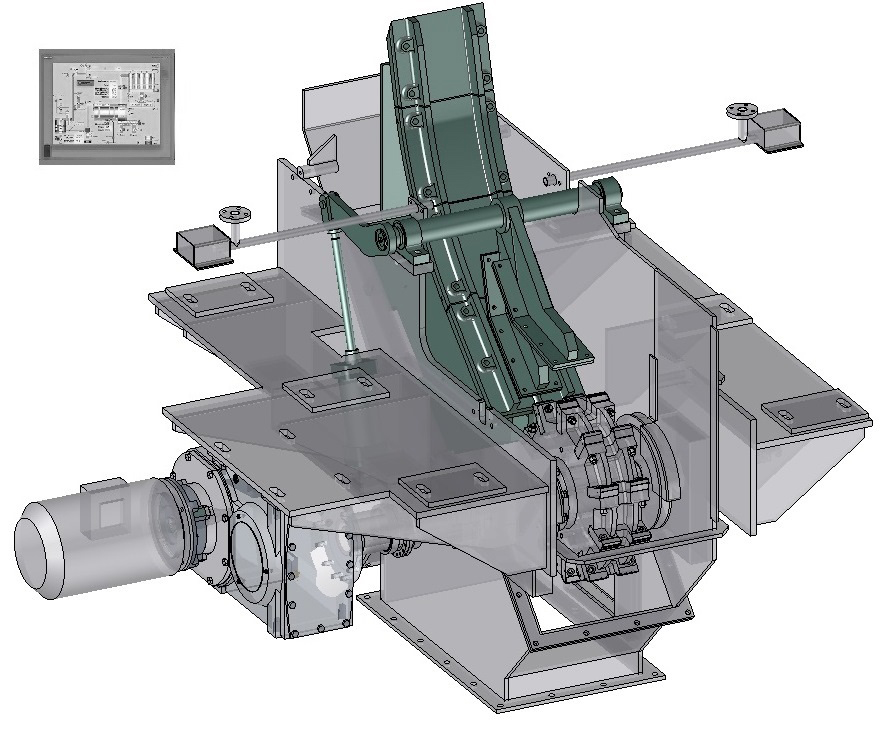
Guide chute
Made of special refractory stainless steel, the separator’s guide
chute conveys the briquettes‐strips from the hot briquetting press to
the separator rotor. The guide chute is equipped with wear plates
and designed for easy and quick replacement. A nose is bolted on
the bottom part of the guide tunnel to contribute in the separation
of the briquettes strips into single briquettes.
It is equipped in its bottom part with a down holder driven by a pneumatic jack.
A system to detect the possible blocking up of flakes in the guide tunnel can be installed.
It is equipped in its bottom part with a down holder driven by a pneumatic jack.
A system to detect the possible blocking up of flakes in the guide tunnel can be installed.
Driving unit
The rotor shaft is driven by a variable speed gear‐electric motor installed at the end of rotor shaft. One frequency inverter installed in the MCC adjust permanently the speed of the rotor shaft though a control loop design in the Control‐Drive cabinet.WATER COOLING SYSTEM & SEAL GAS SYSTEM
Considering the high temperature of the material and in
order to protect the separator, its rotor is protected by a
cooling water system.
Fitted with networks pipes, a set of valves and instruments (temperature sensor, flowmeter, pressure switches), this cooling water system is designed to control and distribute water at required temperature and flow to the rotor of the separator.
Fitted with networks pipes, a set of valves and instruments (temperature sensor, flowmeter, pressure switches), this cooling water system is designed to control and distribute water at required temperature and flow to the rotor of the separator.

Considering the presence of sparks during production
caused by the high flammability of the DRI, and to avoid
re‐oxidation of the DRI, an inert gas (like nitrogen) must be
injected in the separator’s casing to minimize the oxygen
rate of the ambient air (<2%).
Fitted with networks pipes, a set of valves and instruments (flowmeters), this seal gas system is designed to control and distribute seal gas (nitrogen usually) at required flow to defined zone of the separators (casing, blocking sensor…)
Fitted with networks pipes, a set of valves and instruments (flowmeters), this seal gas system is designed to control and distribute seal gas (nitrogen usually) at required flow to defined zone of the separators (casing, blocking sensor…)
Control-automation
A high automation level ensures a constant continuous operation of the associated separator. The control‐drive system is based on signals from the measurement of the rotor speed and power absorbed.
One control loop is combined in the software programming to ensure a constant and proper running of
the separator. This loop is based on interlocking of the separator’s rotor speed following the hot
briquetting press rolls speed.
The control‐drive system and associated supervisory developed by SAHUT‐CONREUR for controlling the Hot Briquetting Unit integrates the following features:
The control‐drive system and associated supervisory developed by SAHUT‐CONREUR for controlling the Hot Briquetting Unit integrates the following features:
- Industrial SIMATIC PC computer suitable for production applications
- Supervising software type WINCC
- Robustness and high availability
- Data acquisition, management and measuring.
- Exchange table provided to transfer main signals to whole plant DCS

